The masonry wall panel element allows you to easily model, analyze and design masonry walls for in plane loads. In this section, we will explain the masonry specific inputs and design considerations. For general wall panel information, see the Wall Panels topic. For masonry wall modeling procedures, see the Masonry Wall - Modeling topic. For masonry calculation considerations and code references, see the Masonry Wall - Design topic. For masonry wall results interpretation, see the Masonry Wall Results topic.
Note:
Setting a maximum Bending Check (Axial & Bending) or a maximum Shear Check controls the rebar which the program chooses for the wall design. A value of 1.0 denotes that the program may choose a rebar layout that is at 100% of capacity.
Note:
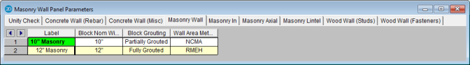
This is the nominal thickness of masonry walls. The program will subtract 3/8" from this value to get the actual thickness. This value is used, along with the value of grout / bar spacing, to determine the effective thickness of the wall. The effective thickness is based on table B3 of the Reinforced Masonry Engineering Handbook, by Amrhein, Copyright 1998.
This option defines how the wall is grouted. If "Partially Grouted" is chosen, then the spacing of grout will be based on the bar spacing defined on the Masonry Out tab.
This option defines where the wall area is taken from. The NCMA option pulls the "An" value from the NCMA TEK 141B document. The RMEH option pulls the "Equivalent Solid Thickness" value from Table B-3a and B-3b from the Reinforced Masonry Engineering Handbook, James Amrhein, 5th edition copyright 1998.
In doing research on these two methods of calculating the area for a masonry wall, the two methods produce very different results. The NCMA values assume face-shell mortar bedding and web bedding around grout-filled cells. The RMEH values assume full mortar bedding (both face-shells and all webs). The Amrhein values also appear to average in the area of horizontal bond beams as well. This would make the area conservative for a self-weight calculation, but unconservative for stress calculations. With these considerations in mind we are defaulting the behavior to use NCMA by default.
See the Masonry Wall - Design topic for the specific calculations regarding NCMA or RMEH.
Note:
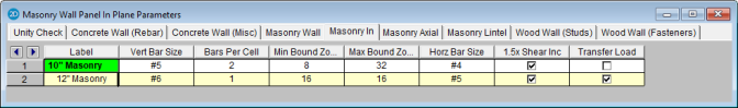
Allows you to define vertical bar size for the boundary zones.
Allows you to define one or two bars per cell in the boundary zones.
Allows you to give a maximum and minimum boundary zone width. The program will then design the width based on 8" increments (1/2 of a block length).
Allows you to define horizontal bar size to be used if horizontal reinforcing is required.
The 1.5x Shear Inc checkbox has been moved to the Seismic Design Rules spreadsheet in the Masonry Walls tab. Please see Masonry Wall - Seismic Design.
This option will transfer in plane loads from regions above and below openings into the regions adjacent to the openings. Note that the design of regions above and below openings will be omitted.
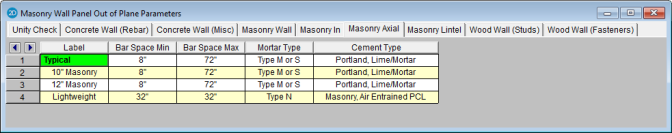
This allows you to give a maximum and minimum bar/grout spacing. If you give a range between the max and min, then the program will optimize the reinforcement spacing according to strength requirements (code checks).
Allows you to specify the type of mortar/cement in the wall. This affects the modulus of rupture (flexural tensile stresses) from Tables 8.2.4.2 and 9.1.9.2.
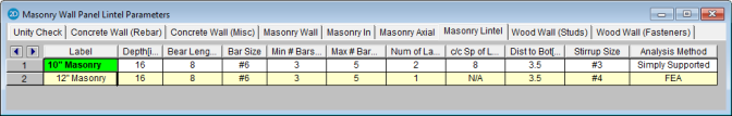
This is the total depth of your lintel.
This is the bearing length at either end of the lintel. This is used to calculate the effective length of the lintel.
This is the reinforcement size for your main reinforcing in the lintel.
This is the number of bars you wish to have in a given layer of reinforcement. If you give a range between the max and min, then the program will optimize the reinforcement spacing based on geometry of the section and also the number of layers that you have defined.
This is an option if you require multiple layers of reinforcement in the lintel.
This is the distance between layers (if there is more than one).
This defines the distance from the centerline of the lowest-most bar to the bottom fiber of the lintel.
This is the size of stirrup that will be added to the lintel if required.
This is the lintel analysis method that will determine the design of the masonry lintel. The Simply Supported analysis method will produce lintel reinforcement design results, which can be seen in the masonry lintel detail report. The FEA analysis method will only display shear and moment diagrams in the detail report for the masonry lintel based on the results of finite element analysis.